3D drawing software user’s manual
This documentation contains use cases for the 3D drawing software.
Object from a primitive solid
You will find in this section some examples of objects realized frim a primitive solide like a cube, a cylinder or a sphere.
Simple object
The object we will realize is a part of a fishing reel that has the following shape:
The overall shape of this part is a cylinder with 14 mm in diameter and 3 mm in height, with a central groove 4 mm wide and 2 mm deep.
There are also two holes of 2.5 mm diameter at 2.5 mm from the edge.
Step 1 : Drawing of the cylinder
|
|
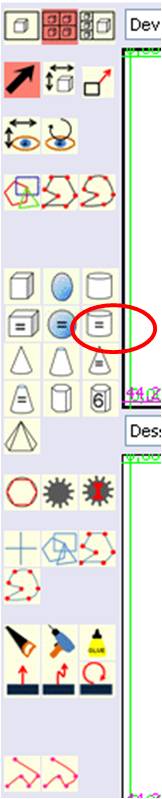
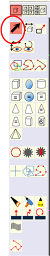
Select the “Cylinder equal” tool.
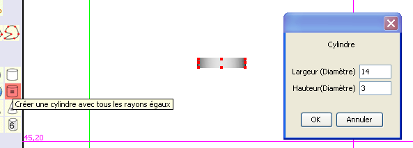
The below dialog window is displayed:
We enter in this window a diameter value of 14 mm and a height value of 3 mm, and then click on the “OK” button.
|
Step 2 : central groove cutting
The part has a central groove 4 mm wide and 2 mm in height which is 5 mm from the edge of the part (5 mm + 4 mm + 5 mm = 14 mm)
We'll cut with the saw after having made a tracing draw.
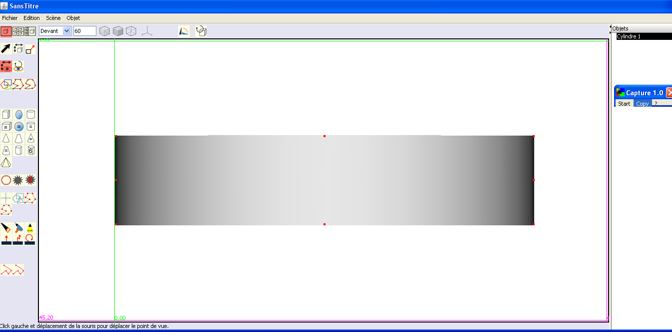
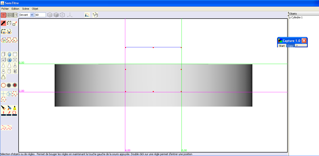
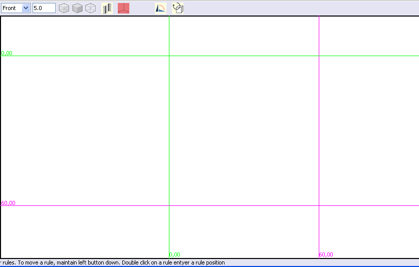
To get most accuracy as possible, we will select one large picture with a zoom of 60.
To position the tracing correctly, we will set the bounds with the rules, starting with positioning a vertical rule to the left of the object.
If
the rule is not positioned exactly along the object, slightly move
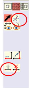
the view with the tool
![]() .
.
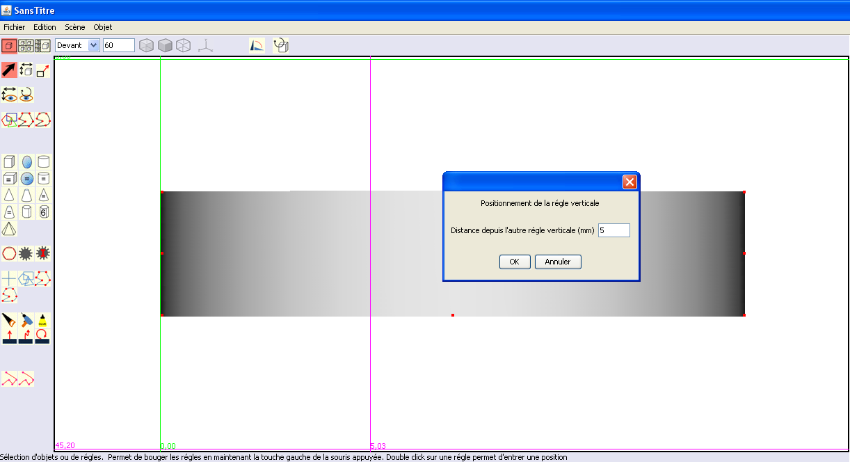
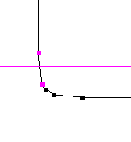
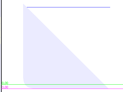
Then position the second rule about 5mm (the distance is displayed in the bottom of the view beside the ruler) of the first one by moving it with the mouse, and then more precisely by double clicking on it and entering a value 5 mm, and then OK.
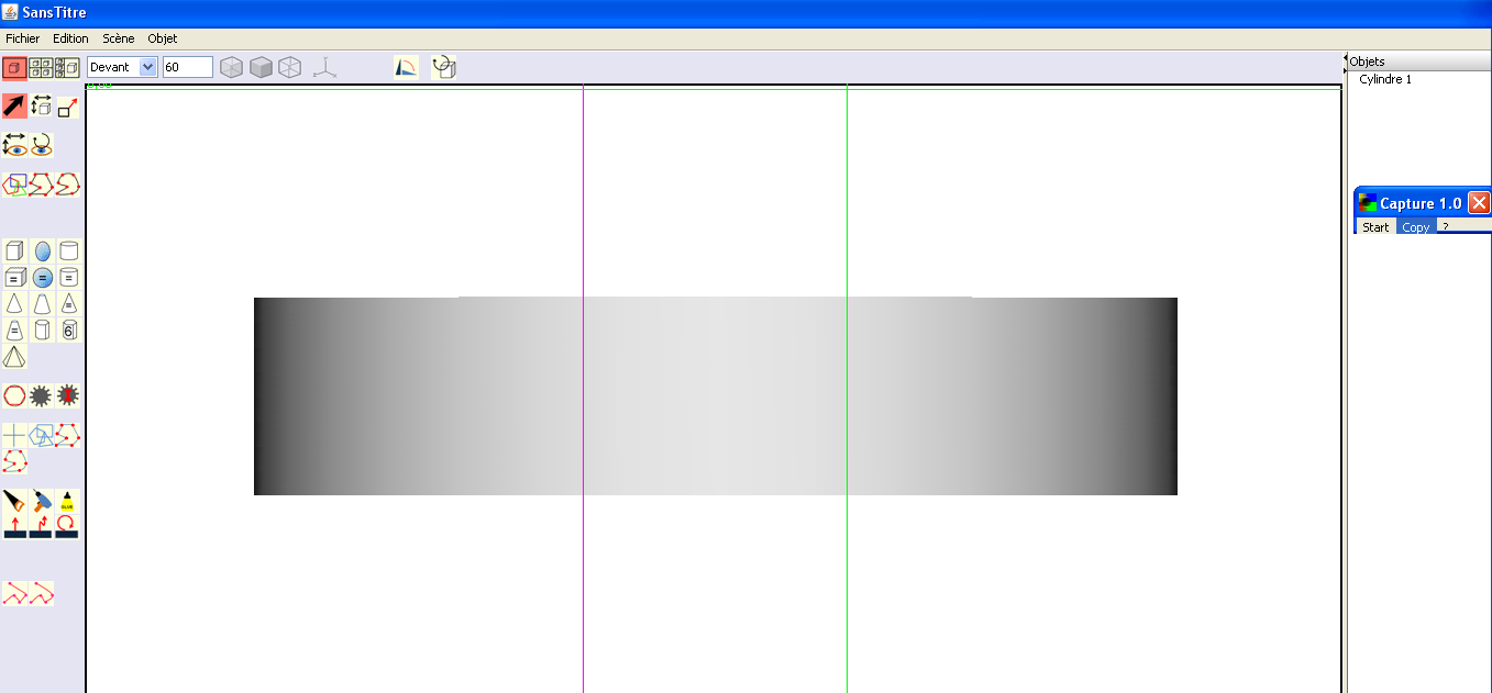
With the mouse, move the left ruler (green in the example) to the right of the other rule (magenta in the example), at a distance of about 4 mm, and double-click the rule and enter 4mm.
This gives the vertical contour of the groove.
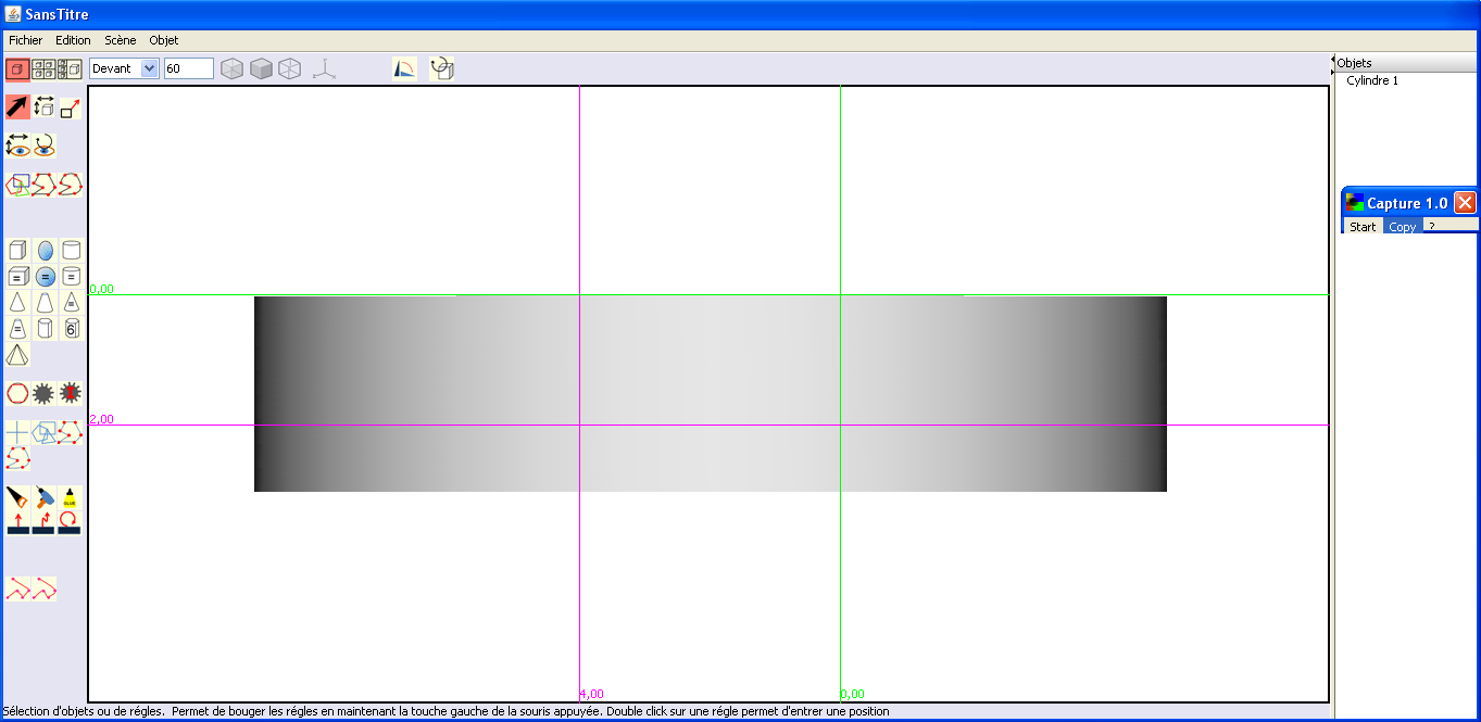
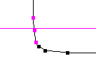
Similarly, a horizontal rule is positioned on top of the object and the other horizontal ruler to 2 mm of it to get the full outline:
|
|
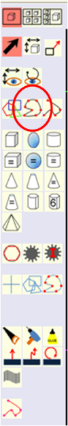
Then
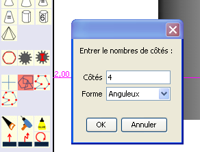
you double click on the tool “drawing a tracing polygon”
4 is the default value, so if you have not previously changed this value, you can skip this step.
|
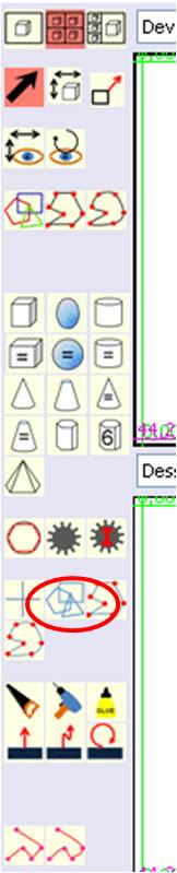
Select
the tool
![]() and
and
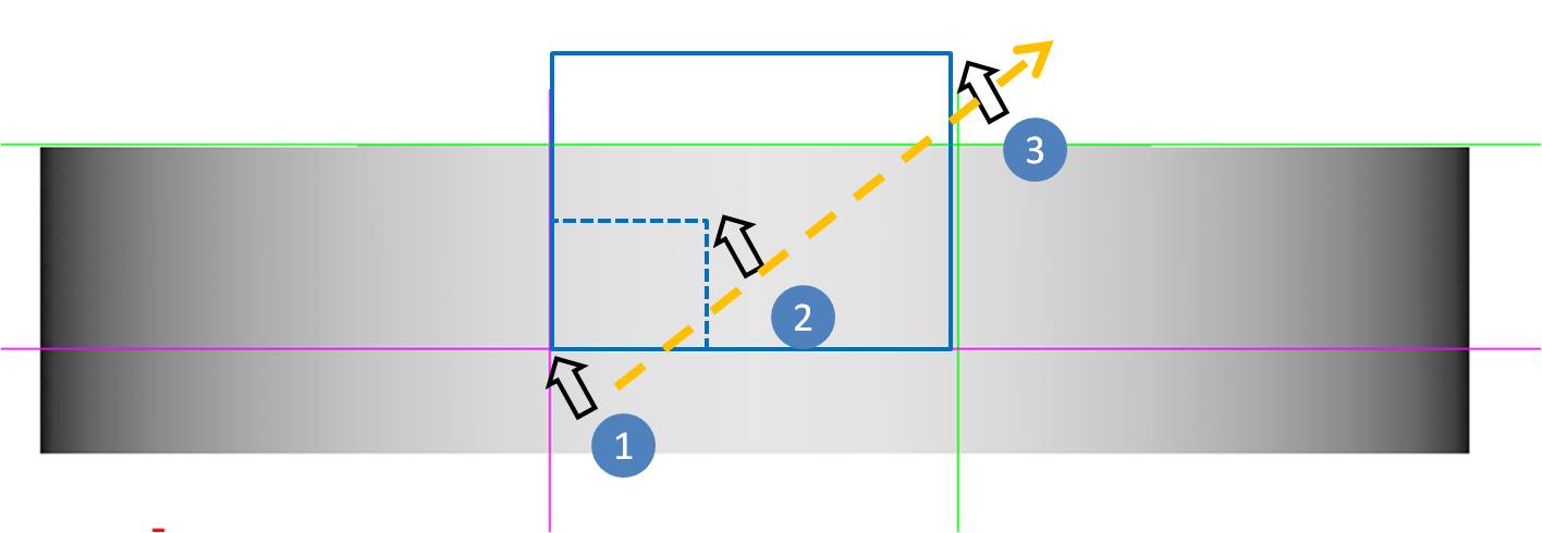
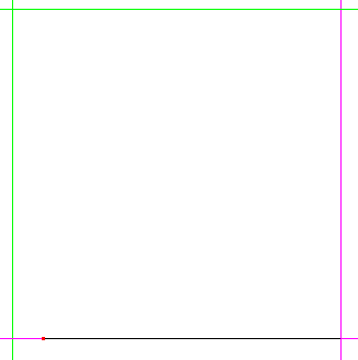
Left click left at the intersection of the two rules at the bottom left and drag with the mouse while holding the left button of the mouse so that the outline of the blue rectangle is aligned on the left vertical ruler, the below horizontal rule and the right vertical ruler.
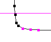
We should get the following result:
The blue line is hidden by the rules. It will appear when you move the rules.
If
the shape of the tracing is not correct, you can adjust it by
selecting it and using the
![]() tool on the red marks.
tool on the red marks.
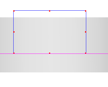
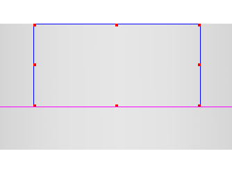
IMPORTANT: The tracing must extend far beyond the exterior of the solid:
|
|
|
|
Good |
Bad If the tracing is at the limit of the surface of the solid, it may actually be a few hundredths of a millimeter below, and when sawing, it will remain a very thin layer sometimes barely visible but that may give bad results when printing the object. . |
You
must then select the blue tracing draw and click on the saw
![]() .
We get the below dialog window:
.
We get the below dialog window:
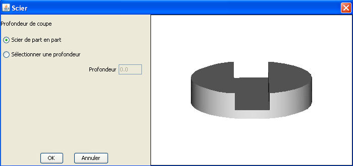
For a little perspective, you must click on the object and move the mouse.
The result seems consistent with what we want, so we click OK.
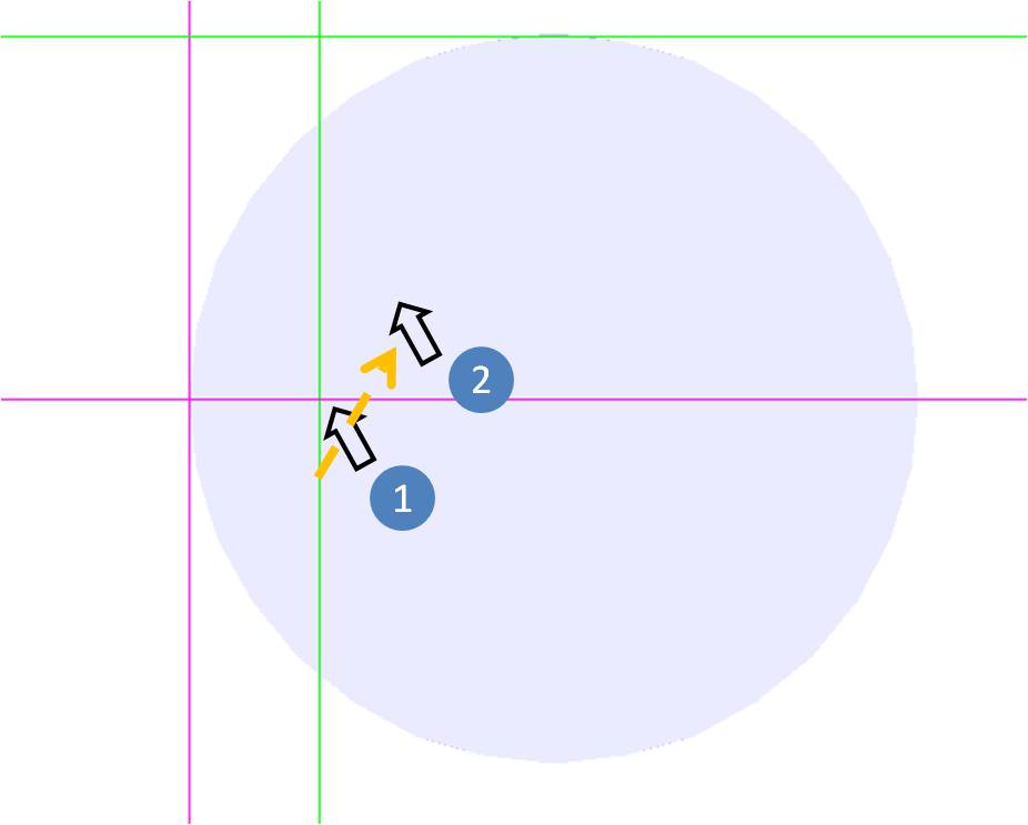
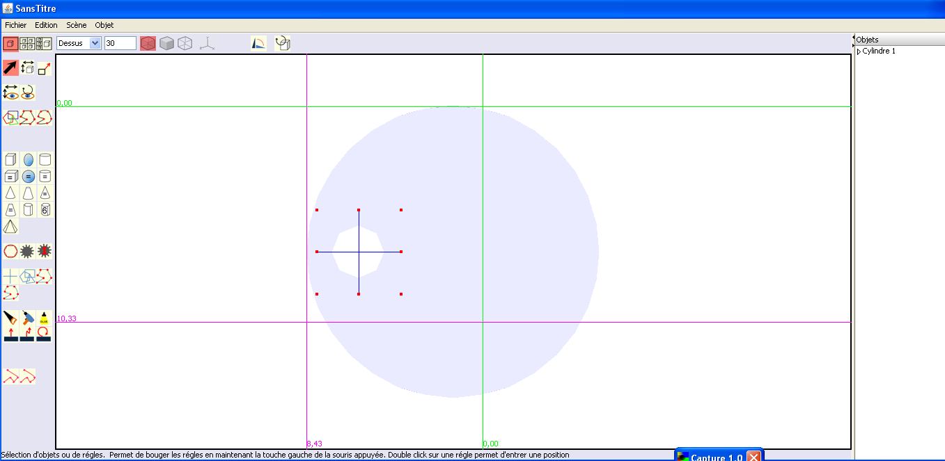
Step 3: drilling of the 2 holes.
There are two holes of 2.5 mm diameter at 2.5 mm from the edge.
We select a view with a zoom of 30, in which we position the rules as follows:
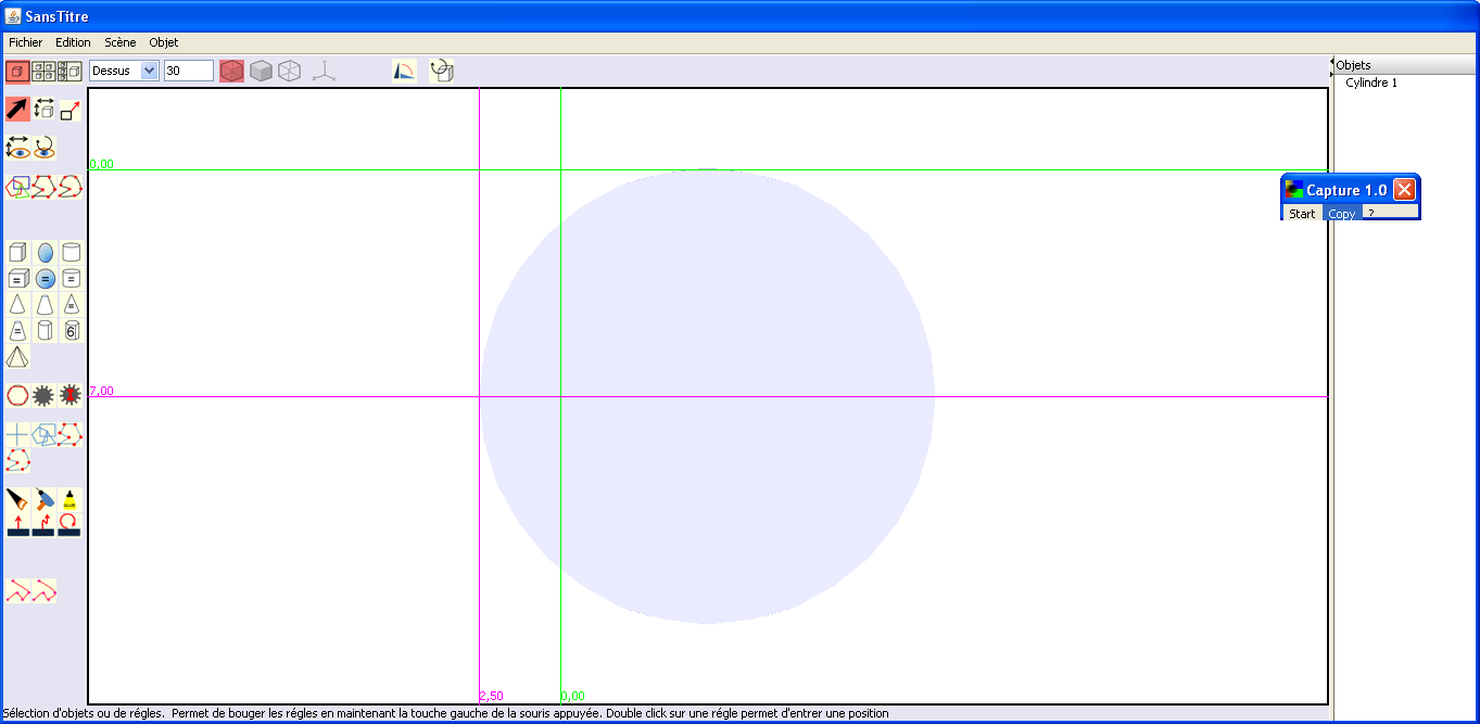
We
select the Blue Cross tool
![]() ,
before clicking where must be the center of the circle, that is to
say, at the intersection of the horizontal ruler at the bottom and
the vertical ruler to the right, and drag with the mouse while
holding the left mouse button.
,
before clicking where must be the center of the circle, that is to
say, at the intersection of the horizontal ruler at the bottom and
the vertical ruler to the right, and drag with the mouse while
holding the left mouse button.
When you release the left mouse button, you cannot see the cross but only the red squares correspond to the fact that it is selected.
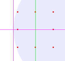
To see the cross, you should move the rules.
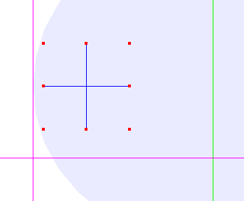
The size of the cross has no matter.
Select
the cross and click on the drill tool
![]() .
The below dialog window is displayed.
.
The below dialog window is displayed.
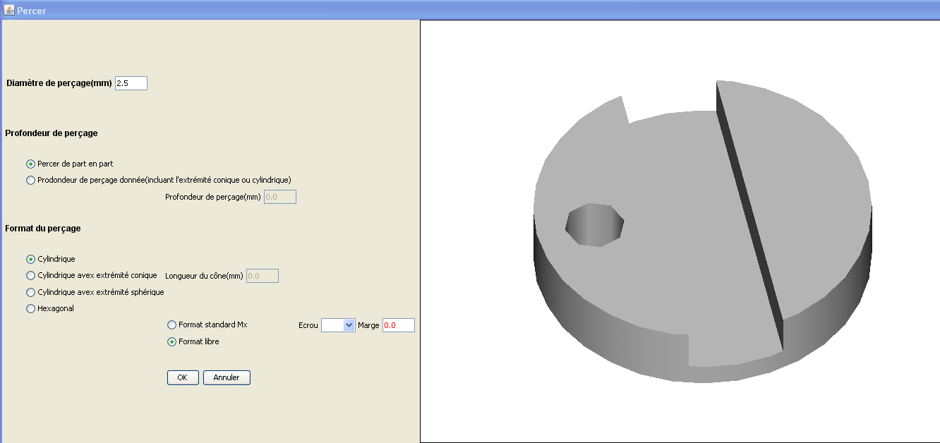
We enter a diameter value of 2.5 mm and then OK.
We select the cross and delete it (otherwise you will not be able to save your work in STL)) :
«Del key
or Menu/Edit/Delete,
or contextual menu (right click on the cross with the mouse).
We
can then select the transparent rendering mode
![]() on top of the view and tselect the view rotation tool
on top of the view and tselect the view rotation tool
![]() to rotate the view around the object (left click in the view and
mouse move) to see the result.
to rotate the view around the object (left click in the view and
mouse move) to see the result.
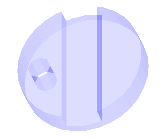
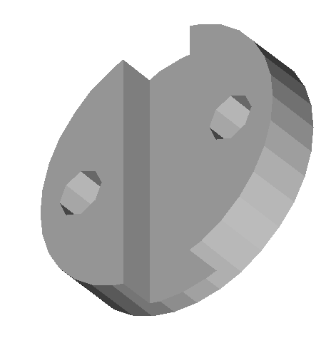
The hole appears hexagonal and not truly circular. This is because we use a large zoom and the hole has a very small diameter.
The drilling of the second hole is similar to the first. This gives the finished part:

Object from a curve
You will find in this section examples of objects realizes from a curve that is then thickened.
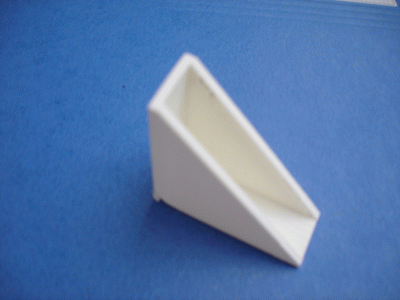
Protection for table corners (Easy object)
The object that we will achieve will help protect a table corner potentially dangerous for young children that might hurt the head hitting the corner.
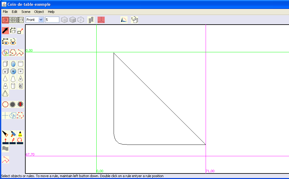
It has the following shape :
|
|
|
We want the length of the two sides being about 60 mm.
The thickness of our table is 16 mm and we decide that the wall thickness is 3 mm.
WARNING: If you want to make this item. The measurement of the thickness of the table must be very precise and it is preferable to minimize of 0.5mm if you want the protection holding well on the corner of the table.
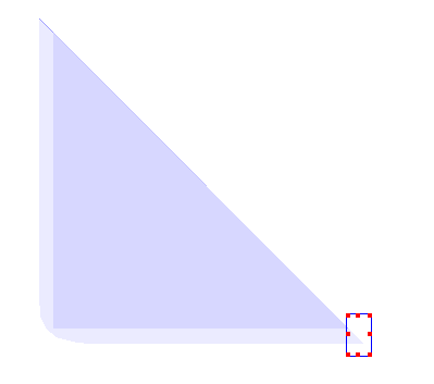
Step 1: Draw the outline of the object
|
|
We first select a single view and viewed from the front . To assist in the achievement of the tracing, with the arrow tool selected, we set the 2 vertical rules to 60 mm from each other. The same is done for the two horizontal rules. Reminder: To move the rules, left click on the rule and move the mouse or double click on the rule and enter the wanted distance between the rules .
|
|
|
|
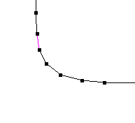
We then select the "freehand closed curve" tool with which we make a rough draw that we will then refine in the curve editing window.
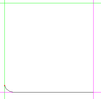
We draw a first segment by clicking at the intersection of the two red rules and then at about 1cm from the intersection of the red horizontal rule and of the green vertical rule.
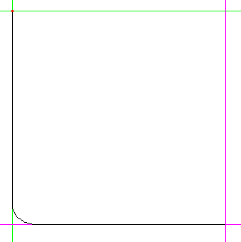
We then draw a rounded corner made of small segments by successive clicks to set 4 or 5 points. It will then be possible to add or delete points in the curve editing window.
We then define the second side.
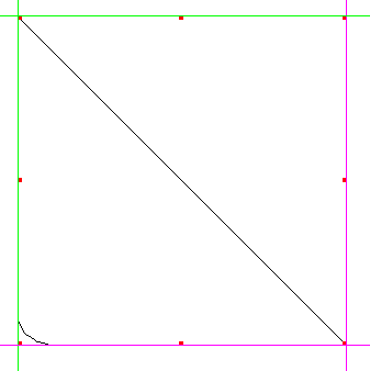
And we close the curve with the enter key or by double-clicking on the last point (last point of the previous image ).
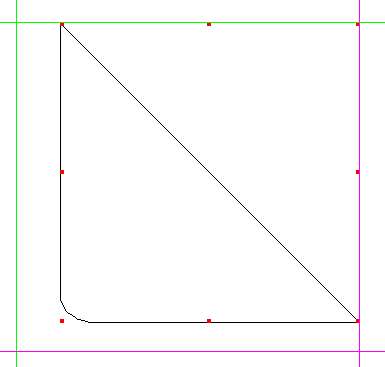
We can set aside the rules to see the plot.
|
Step 2: Finishing the outline of the object
The curve we have just outlined being selected, we will edit it by "Object/Edit object" in the menu of the window.
This opens the curve editor window that looks as follow:
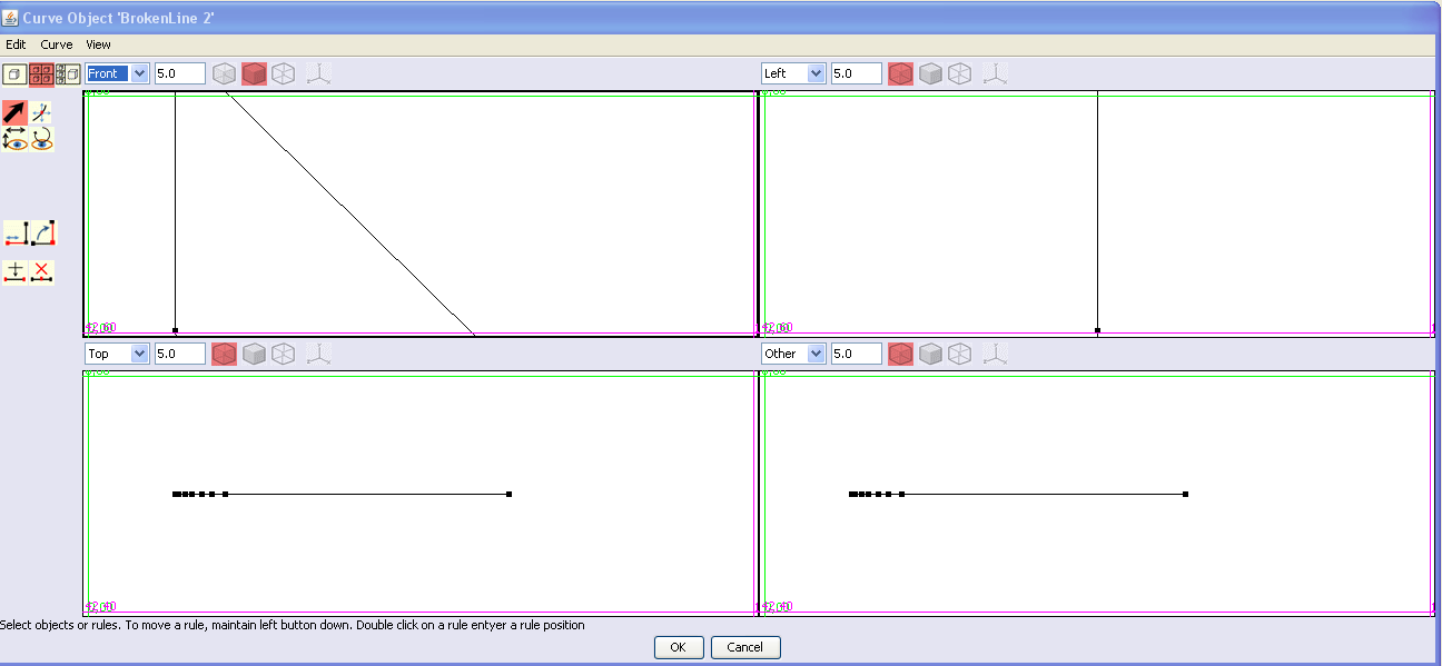
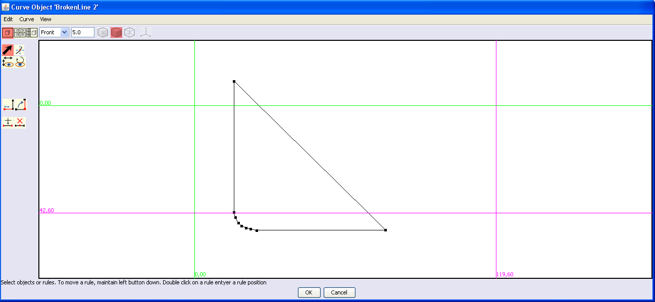
In general you edit in this window planar curves. So it is better to switch to one view in order being more comfortable to edit the curve.
|
|
|
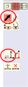
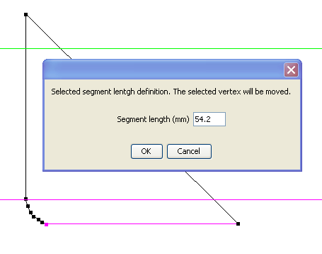
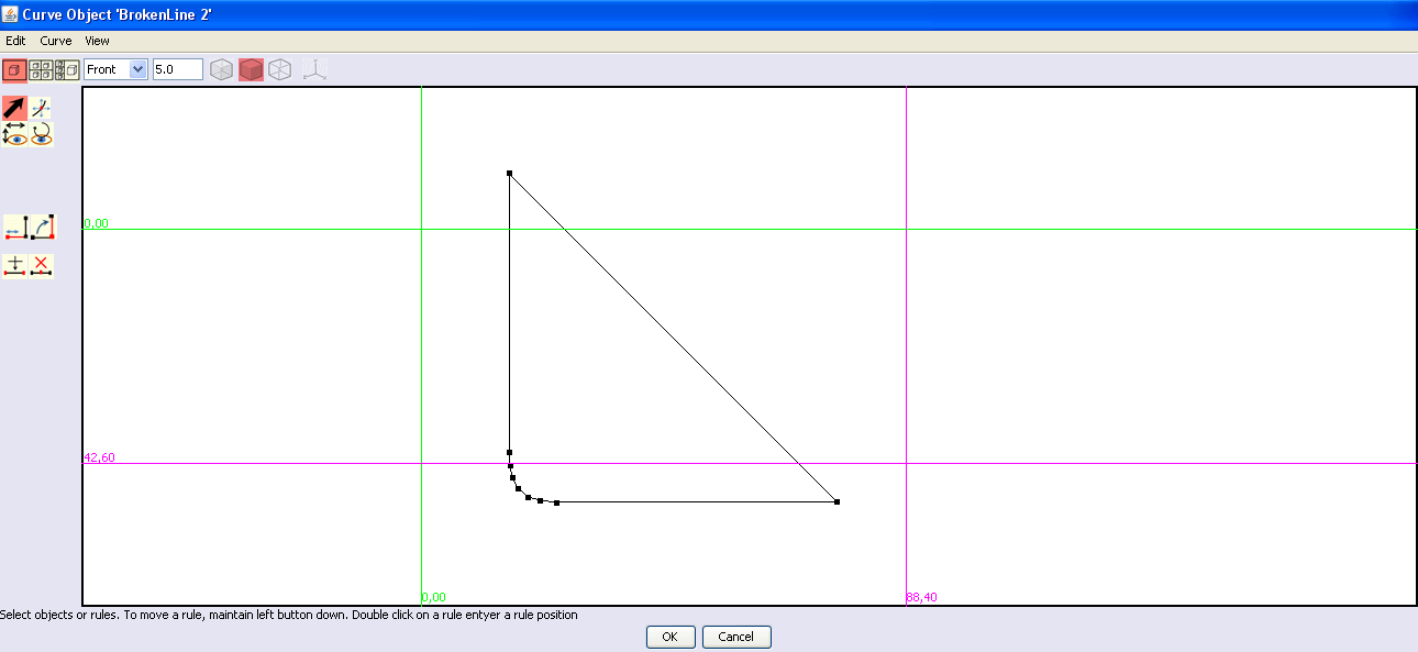
We select the horizontal segment at the bottom of the draw and the point at the left end of this segment with the selection tool (arrow). The selected item are colored in red. We then click on the segment length tool.
A window appears indicating that our segment is 54.2 mm.
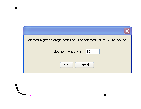
We enter the desired value, i.e.50 mm and then OK
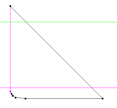
We select the vertical segment on the left of our draw and its low end and like previously we set the length to 50 mm.
|
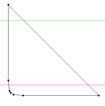
We will now improve the rounded part of the draw.
|
|
|
We consider that we have not drawn enough points for this round and that we should add a couple of points. We select two points.
The
insert point tool
We add a second point in the same way and others if needed.
Then
with the move points tool
For more accuracy, it is recommended to zoom in on the part of the object you are working on
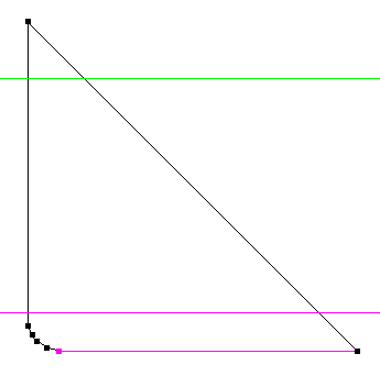
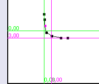
It is advised materializing the future inner contour with a vertical and a horizontal rule as shown beside in order to check that there is enough material remaining at angle level.
|
The required draw being obtained, we click OK.
Which brings us back to the main window.
Step 3: Make a solid from the outline
We will now make a solid from this curve.
The thickness of our table is 16mm and we want the 3mm .walls.
We must do a solid with a thickness of 16 + 2x3 = 22 mm.
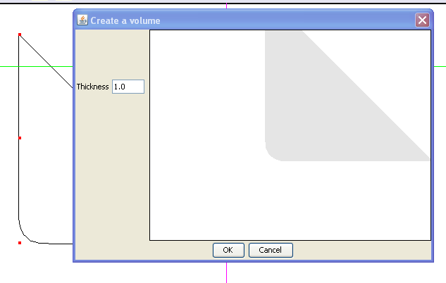
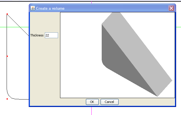
|
|
We select the curve and we click on the thickening tool. We get the following dialogue:
We enter the desired thickness, 22 mm, and we can see the result by clicking on the drawing in the dialog box and making movements with the mouse.
We click OK to perform the operation.
|
Step 4: Carve inside the object
Now we need to carve inside the object.
For this, we use the saw tool, in the same way as for a primitive solid.
We start by defining the part we should saw with the rules.
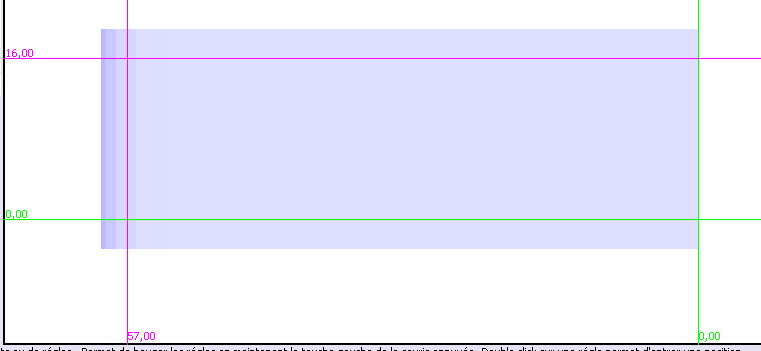
We change the view from front to top and we put the green vertical rule at the edge of the object to the right. The length being 60 mm and the wall thickness of 3 mm, it is necessary to position the second vertical rule, red, to 60-3 = 57 mm
We set the red horizontal rule at the bottom edge of the object and then we position the green horizontal rule to 3 mm.
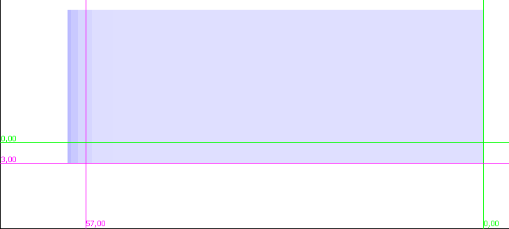
We then move the red horizontal rule above the green and we put it at 16 mm, i.e. the thickness of our table.
We
select the tool that allows drawing a blue line with a polygon shape
![]() and we draw a square over our rules, except on the right where, as
seen previously, it is better to draw it a little bit outside of the
solid.
and we draw a square over our rules, except on the right where, as
seen previously, it is better to draw it a little bit outside of the
solid.
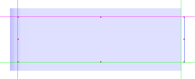
The blue line square being done, you can move the rules to see it.
Below views from different angles.
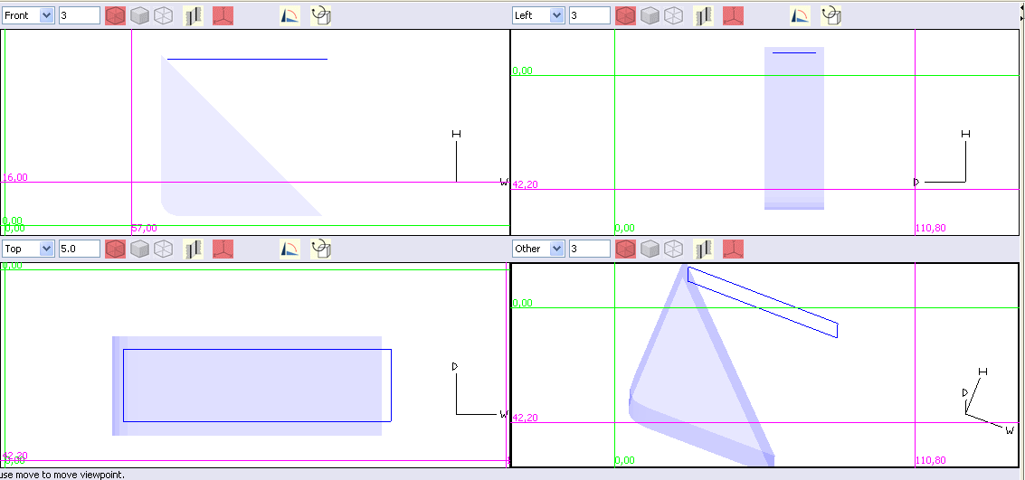
.
Now we need to cut, but how deep ?
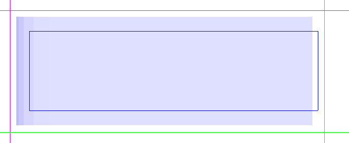
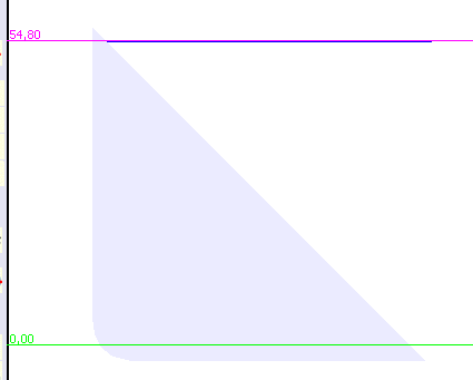
We set the rule, the green in our case, 3 mm from the edge of the object:
We then set the second rule, the red in our case, and we get a distance of 54.8 mm , which is our sawing depth.
We select the blue line and we activate the saw tool.
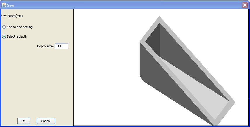
We select a depth of 54.8 mm and we click OK.
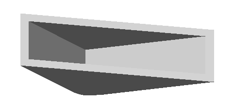
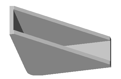
Step 5: Finishing the object
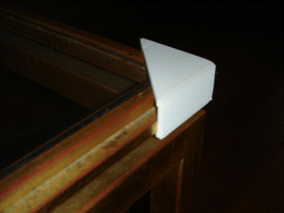
We can either let the object as such or cut the 2 pointed ends as follows.
This will give the following result:
Build of a solid from an SVG file
You will open an SVG file format.
For example, the SVG file with this content:
<svg width="12cm" height="4cm" viewBox="0 0 1200 400"
xmlns="http://www.w3.org/2000/svg" version="1.1">
<desc>
Exemple d'ellipses dans un rectangle - example of ellipses in a rectangle
</desc>
<rect x="1" y="1" width="119.8" height="39.8" fill="none" stroke="blue"
stroke-width="2" />
<g transform="translate(30 20)">
<ellipse rx="25" ry="10" fill="red" />
</g
<ellipse transform="translate(90 20) rotate(-30)" rx="25" ry="10"
fill="none" stroke="blue" stroke-width="20" />
</svg>
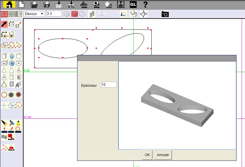
will give this result:
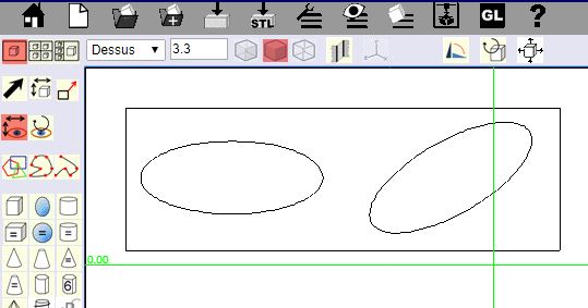
You will then select several curves to get a solid.
By
selecting all the curves imported from the above SVG file end by
clicking on
![]() you will get this result:
you will get this result: