


3D modeling reference manual
This documentation includes two main parts:
The description of the main window
The description of the curve editing window
This documentation is completed by the 3D modeling tool user’s manual that provides examples of using the tool to create objects.
Main window
The main window shows when starting four views that let you see the same object from different angles.
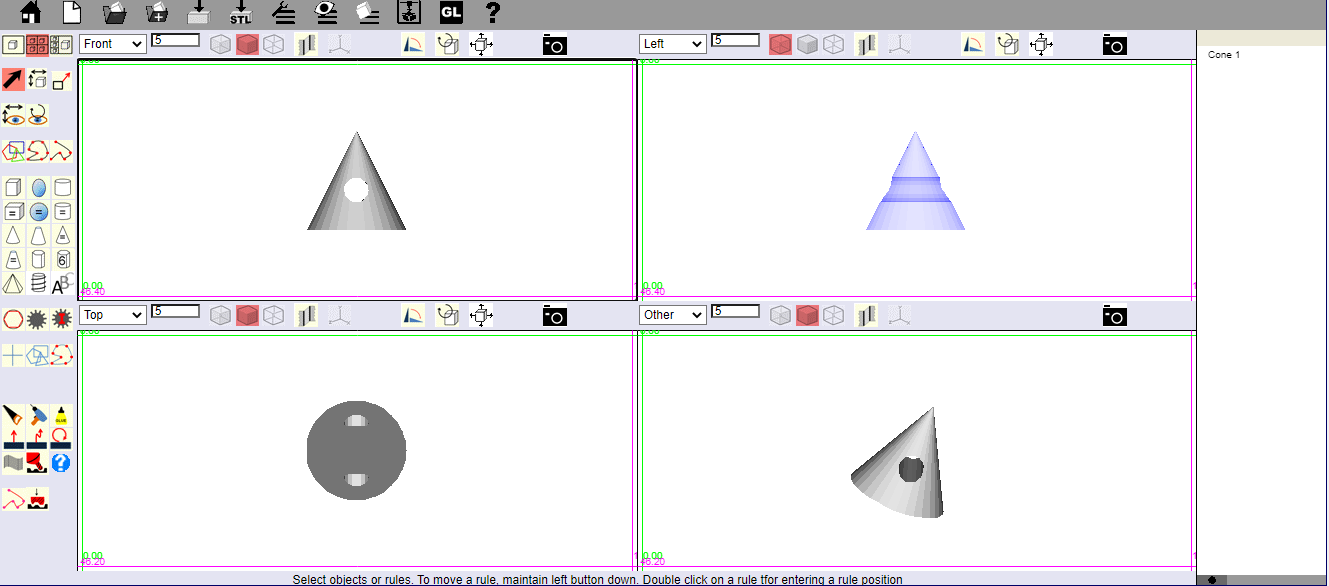
The commands available in the main screen are:
The menu bar at the top left of the window,
A vertical toolbar that occupies the left of the window
A toolbar at the top of each view.
There is also a context menu that appears when the cursor is over a selected object and a right mouse click is performed.
You will find later in this document
The description of the menu bar (Chapter "Menu"),
The description of the vertical toolbar (Chapter "vertical Palette"),
The description of a view with its toolbar (Chapter "View").
Menu
![]()
Exits the modeling tool to return to the home page of the site.
Exits the current modeling and start a new modeling. If the previous modeling is not supposed being saved, the software will ask if you want to save it or not.
Open a file in native(.vwb), STL(.stl) or SVG format from your local disk(s). The content of the application is replaced by the content of the opened file.
Equivalent
to
![]() and then
and then
![]()
Open a file in native(.vwb), STL(.stl) or SVG format from your local disk(s).
The content of the opened file is added to the content of the application.
Save a file in native(.vwb) format on your local disk(s). It is seen by the browser as a file download and the browser applies the rules defined in its settings, i.e. :
Either a default download directory and in this cas there is no dialog.
Or a file chooser dialog box asking for the download directory and the file name.
With Edge, the behavior is slightly different. A dialog box asking for a file name is displayed.
Save a file in STL(.stl) format on your local disk(s). It is seen by the browser as a file download and the browser applies the rules defined in its settings, i.e. :
Either a default download directory and in this cas there is no dialog.
Or a file chooser dialog box asking for the download directory and the file name.
With Edge, the behavior is slightly different. A dialog box asking for a file name is displayed.
Edit
Actions that can be performed in the Edit item of most software can be found in this menu item.
Undo: Undo the last action. Shortcut: Ctrl + Z
Redo: Redo a previously undo action. Shortcut: Ctrl + Y
Cut: Copy the selected object to the clipboard and deletes it. Shortcut: Ctrl + X
Copy: Copy the selected object to the clipboard. Shortcut: Ctrl + C
Paste: Paste the previously cut or copied object. Shortcut: Ctrl + V
Delete: Deletes the selected object. Shortcut: Del
Select All: Selects all objects. Shortcut: Ctrl + A
Vue
This item includes the following actions:
Grid: Set a background grid for views.
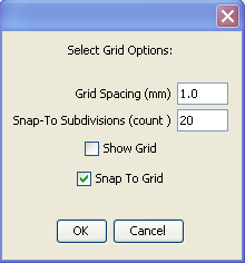
Grid spacing: Spacing in millimeters between the lines displayed by the grid.
SnapTo Subdivisions: Indicates the number of subdivisions between grid lines. These subdivisions are not visible and are only used if " Snap to grid " is activated. If this option is enabled, an object that you move or change the size you will automatically move these subdivisions. For example, if the grid spacing is 5 mm and you set 10 subdivisions, the object will move 0.5 mm in 0.5 mm.
Show grid: Displays the grid when selected.
Snap to grid: Allows objects to automatically position on a sub division of the grid.
Include all objects: Adjusts the zoom so that all objects are encompassed in the view.
Object
This item includes the following actions:
Modify object : Displays a window that allows you to change the characteristics of the selected object. Window depends on the object and is identical to the window object creation. This command applies only to primitive objects (cube, cylinder, ...) that have not been altered by sawing, drilling or bonding.
Edit object: Displays a window that allows you to change the object. Applies only to objects of curve. type.
Rename Object: Displays a window that allows you to change the name of the object. The name of the object appears in the window under "objects" to the right of the window.
Hide Selection: Makes the selected object completely transparent and revealing objects that are behind the object.
Show Selection: Makes an object visible again. The opposite of the previous command.
Show All: Make all objects visible again.
Activation or deactivation of the Webgl option, if it is available in your browser.
Webgl take benefit of the graphical board of your computer to display the 3D objects.
Depending on the browser, the navigator and the graphical board, the Webgl activation can lead to more or less good results.
This icon allows choosing the option that you are preferring.
![]() Webgl is deactivated. You will activate it by
clicking this icon.
Webgl is deactivated. You will activate it by
clicking this icon.
![]() Webgl is activated. You will deactivate it by
clicking this icon.
Webgl is activated. You will deactivate it by
clicking this icon.
Vertical toolbar
The tools in this bar are the ones you'll use most often to create an object.
Here we are trying to do the better description of the operation of these tools, but the best to master these tools well once the principle is understood to test by yourself. You will find that by trying, these tools are actually quite simple to use.
This bar contains 9 sets of tools that are described below from top to bottom.
Selecting the layout of the views
![]()
When you open the drawing tool, it has by default 4 views. This group allows you to display 1 large view, 4 small views or 3 small views and 1 large view.
|
|
|
|
|
|


One large view allows you to work with greater comfort on the details of the object.
With the display of four views, you can see the object simultaneously from multiple angles and to better understand the actions performed.
Display 3 + 1 is intermediate.
With practice, you will naturally select the layout that you feel most comfortable for the action you are performing.
Actions on the object
![]()
Tool
on the left
![]() is the tool that is selected by default (
is the tool that is selected by default (![]() ).It
allows you to select an object in the views or to move the rules.
).It
allows you to select an object in the views or to move the rules.
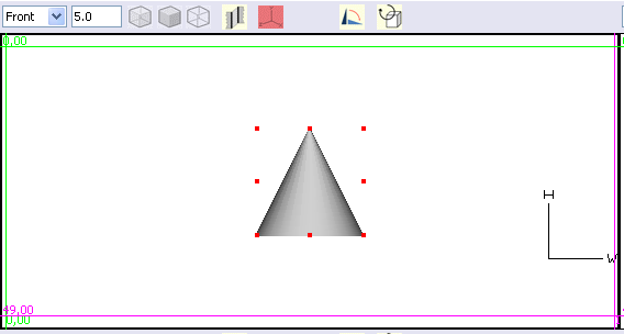
A selected object in a view is recognizable by the fact that it is surrounded by red marks.
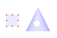
The cube is selected. The cone is not.
To select multiple objects, click the first object, then hold < Shift> key and click to select other items.
This tool also allows you to move the green and magenta horizontal or vertical rules present in the view by clicking on them and dragging the mouse.
The chapter "View" describes in detail the use of these rules.
The
tool in the center
![]() moves the selected objects. It is the object that moves and it moves
in all the views. If you have drawn several objects, you will see
that the selected object moves relatively to other objects.
moves the selected objects. It is the object that moves and it moves
in all the views. If you have drawn several objects, you will see
that the selected object moves relatively to other objects.
Do
not confuse with the tool that has an
effect on the view
![]() described in the following paragraph and that moves the view and not
the object.
described in the following paragraph and that moves the view and not
the object.
The
tool on the right
![]() changes the dimensions of a selected object by clicking on a red
handle and dragging the mouse.
changes the dimensions of a selected object by clicking on a red
handle and dragging the mouse.
Actions on the view
![]()
The
tool on the left is used to move horizontally and vertically the
vision of the object in the view. The
objects do not move. This
can be compared to a camera that moves horizontally and vertically in
front of objects. One
sees a shift only in the view in which you are working, unlike the
tool
![]() .
Therefore not to confuse these two
tools.
.
Therefore not to confuse these two
tools.
The tool on the right allows rotating the view around the objects. Again, the objects do not move. This can be compared to a camera that rotates around objects.

This tool is extremely useful for well perceiving the shape in the space of the object that was drawn.
Drawing freehand curves
![]()
This group of tools allows you to draw closed planar curves that can then be raised to create a solid, or open or closed planar curves that allow to create a hull.
After creation, their shape can be changed (Move, add and delete points, smoothing) through the "Object/Edit Object " command of the menu.
It is used as soon as it is needed having a volume with a particular section. To understand the importance of this group of tools, it is advisable to look at the chapters “creating an object from a curve " and "creating an object with the hull tool" in the documentation of use of 3D drawing software.
The
tool on the left
![]() can draw triangles, rectangles, and more generally polygons.
can draw triangles, rectangles, and more generally polygons.
A double-click on this tool allows selecting the number of sides and the form: Angular, interpolation or approximation. If you plan to change the shape then it is best to choose "Angular". After editing the points of the object, you can then modify the shape to interpolation or approximation and define a smoothing factor that you can apply to all points or only to some selected points.
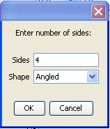
The number of sides being selected, you then left click in a view drag the mouse. The shape appears. Finally, you release the mouse.
The
tool in the middle
![]() creates a closed curve point by point.
creates a closed curve point by point.
A double click on the icon to select the method used to draw the curve.
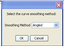
It is recommended to use the "Angular" default method, because generally you will then edit the curve point by point in the “Edit curve” window so that the shape of the curve corresponds precisely to what you want to draw.
After editing the points of the object, you can then modify the shape to interpolation or approximation and define a smoothing factor that you can apply to all points or only to some selected points.
Each click with the mouse creates a point and a segment between this point and the previous point. To complete the curve you can:
Double click when you draw the last point
Press the “Enter" key after having drawn the last point.
The
tool on the right
![]() works the same way as the previous one but creates an open curve.
works the same way as the previous one but creates an open curve.
Open curves are to be used exclusively to prepare a form that you will then cover with the “Hull” tool.
Drawing solids
When you leave the cursor over a tool, a text appears to indicate which kind of solid will be created by this tool.
Each of these tools allows creating a solid, that is to say an object with a volume. The objects created are said primitive and are characterized by well-defined dimensions.
When you click on one of these tools, a special dialog window appears to ask the characteristics of the object. For example, for a cylinder:
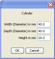
Width corresponds to the diameter in millimeters of the cylinder in the width direction.
Depth corresponds to the diameter in millimeters of the cylinder in the direction of depth.
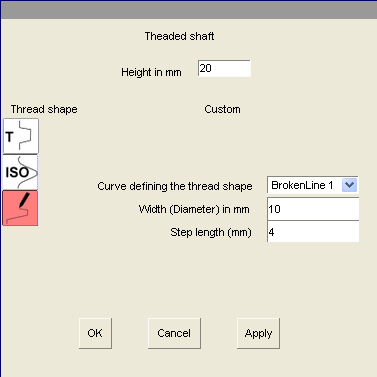
Drawing solids : Threaded shaft case 
The threaded shaft dialog window is a little bit more complex than the one of the other primitive solids.
Think moving the dialog window to see the created solid. You will see the applied modifications.
|
|
You can choose the thread shape through the icons under the “Thread shape” caption. The displayed fields depend on the shape. For a trapezoid thread you should enter the step, the internal height that must be less than the step, the depth of the thread and the external height.
For a “Metric ISO” thread, the thread shape is computed from the diameter. |

|
|
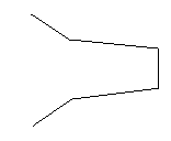
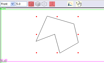
With the “Custom” option, you can create a threaded shaft having a given and previously designed curve as shape. You should select the curve you want to use and define the diameter and the step of the threaded shaft. The curve must be an open curve. The selected curve will be resized in way having the 2 endpoints distance being equal to the step. |
|
|
Example of curve that can be used to define the shape of the thread. The curve will be automatically resized to have the distance between the 2 endpoints equal to the given step.
|
Make a solid having a text shape 
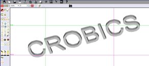
You
can make a solid text object by clicking on the button
![]()
This
object can be combined with other objects.
WARNING: Using this feature can lead to long processing times, depending on the character count and the selected font.
If you want to engrave a text on a solid, you should first make a text and then transform it in milling tool. You should then apply the tool on the solid you want to engrave( See: “Milling with a solid transformed to a tool”)
Warning: This action can lead to long computing time.
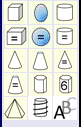
Drawing predefined curves
![]()
Similarly to tools for creating freehand curves, this tool group can draw closed planar curves that can then be raised to create a solid. Here the curves have predefined shapes for which parameters should be provided.
After creation, their shape can be changed (Moving, adding and deleting points, smoothing) by the “Object/ Edit Object” command of the menu.
The
tool on the left
![]() creates a polygon inscribed in a circle.
creates a polygon inscribed in a circle.
The
tool in the middle
![]() creates a simple gear.
creates a simple gear.
The
tool on the right
![]() creates an involute gear.
creates an involute gear.
Draw of tracings
![]()
These tools make the tracings that are required before sawing or drilling a solid.
The tracings made by these tools will be linked to an object. It is therefore necessary to select an object before you select one of these tools.
The resulting tracing is positioned on the surface of the selected object. The positions of sawing and drilling will be defined from the position of the tracing.
In some special cases related to the shape of the object on which we want to act, the tracing can be wrong position. In this case you must manually correct the positioning by selecting and moving the tracing.
Except the blue cross, the other lines can be edited in the same way as other curves before starting a sawing action.
The
blue cross tool
![]() draws a blue cross whose center defines the point where the drill
will work (see next paragraph). You must select an object, select the
blue cross, click where you wish to drill and stretch by moving the
mouse.
draws a blue cross whose center defines the point where the drill
will work (see next paragraph). You must select an object, select the
blue cross, click where you wish to drill and stretch by moving the
mouse.
After using the drill, the blue cross remains in place. This allows, for the same position, drilling with different diameters and different shapes.
It is best to progress from the shallowest to deepest hole when drilling several times in the same location.
The other two tools are working identically to the tools that are described above for the drawing of freehand curve.
Unlike the blue cross, tracing curves are automatically deleted after using the saw.
You can copy/paste the sawing outlines (in blue color) and the crosess that represents the centering marks for drilling (in blue color)
The copy is attached to the object to which the copied curve or cross is attached.
Tools

Saw,
drill and glue
![]() act on the solids.
act on the solids.
Thickening,
thickening along a guiding curve and ring thickening (lathe)
![]() allow to thicken (or raise) a previously drawn curve (freehand curve
or predefined curve)
allow to thicken (or raise) a previously drawn curve (freehand curve
or predefined curve)
The
hull tool
![]() allows coating a set of selected open or closed curves.
allows coating a set of selected open or closed curves.
Saw
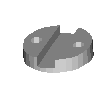
Selecting this tool after you have made and selected a tracing as a curve (see above) opens the following dialog:
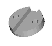
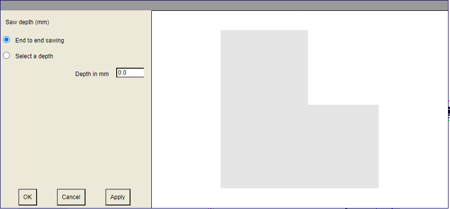 It
was in this case made a square tracing on a
cube.
It
was in this case made a square tracing on a
cube.
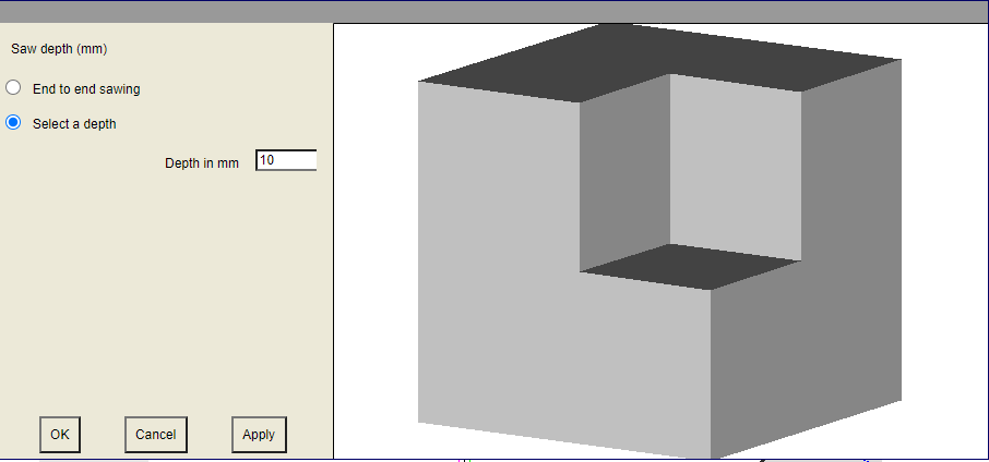
The default selection is “End to end sawing”, i.e. sawing through.
You can also select the option "Select a depth" and enter a depth of cut.
Then click on the apply button to apply the option..
By clicking on the object in the right pane and dragging the mouse while holding the left button of the mouse you can rotate the object to get a better view of the expected outcome.
Drill
Selecting this tool after you have made and selected a blue cross tracing (see above) opens the following dialog:
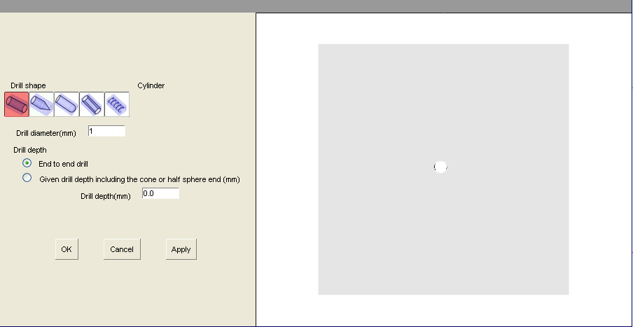
You can select the drill format thanks to the icons under the "Drill shape" caption.
The drilling can be :
Cylindrical (Default option)
It is by default a cylindrical end to end drill of one millimeter in diameter.
Drill diameter allows you to define the drill diameter in millimeters.
You can also set a drilling depth.
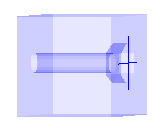
Cylindrical with a conical end
You must define the length of the cone, which is included in the total drilling length..
Cylindrical with a spherical end
With that option, you can also drill a spherical hole if the drill length is less than or equal to the drill diameter.
Hexagonal
The hexagonal drill is useful if you want to insert a space for a nut. You can work with a free format. In that case the hexagon has a diameter equal to the drill diameter. You can also use the standard Mx format option. In that case the nut "drop-down list” allows you to select a standard nut size with a diameter and a predetermined depth. The margin value given by default is the necessary margin. You can change the margin.
Threaded drill
Allow drilling a threaded cylinder.
The options proposed in this case are the same that the one proposed for the draw of a threaded shaft. It is advised reading the documentation on that topic before using that option.
If you need to drill several holes of different shapes in the same place, it is best to progress from the hole with the largest diameter and the smaller depth to the with the smaller diameter and the larger depth.
WARNING : The cross that allows drilling is not automatically removed in order to be able to drill several holes with different shapes in the same place. You must then delete it manually, in particular to be able to save your work in STL format.
WARNING : The options are only applied after click on the "Apply" button.
ADVICE : To get a good understanding of how it works, you should try the different options with a simple case, such as the drilling of a cube, for example, and see the results.
Glue
This tool allows you to glue two selected objects. To give a result that can then be printed correctly, it is necessary to have between the two objects to be glued a sufficiently large intersection, about 0.1 or 0.2 millimeters.
|
|
|
|
|
Bad |
|
Good |
After selecting two objects, click on the "Glue" tool. A window showing a view of the result is displayed:
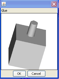
OK confirms the gluing action. Cancel cancels the gluing.
Thickening of an object 
Allows you to create a volume from a curve.
We creates, for example, the following curve from the curve creation tool:
Select the curve and click on the thickening tool. The following dialog window is displayed:

The sole parameter to set is the thickness that you want to give the object.
It is possible selecting several curves to get a solid.
For example:
By
selecting the three curves and by clicking on ![]() you
will get this result:
you
will get this result:

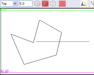
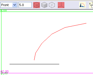
Thickening along a guiding curve 
This tool works on the same principle as the previous tool, but instead to thicken the object perpendicular to the surface of the curve, it thickens along a guiding curve.
Creating a guiding curve is described below but is similar to creating freehand curves explained previously.
If we take the example used in the previous tool description, the curve to thicken is drawn in the top view window. A guiding curve is plotted in the front window view.
|
|
|
|
You
must then select the curve to thicken and the guiding curve, and
click on the
![]() tool.
tool.
You get the following preview window:
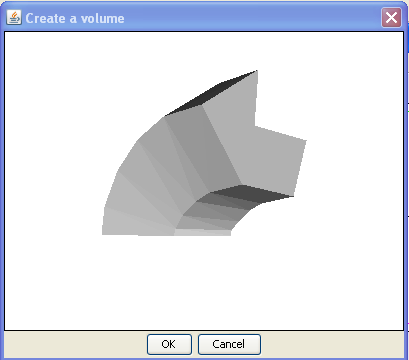
Then click on OK to finish the action.
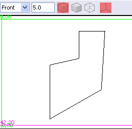
Ring thickening (lathe) 
This tool is extremely important to create circular objects.
It creates a solid by rotating a closed curve.
For example, consider the following freehand curve:
Select
the curve and click on
![]()
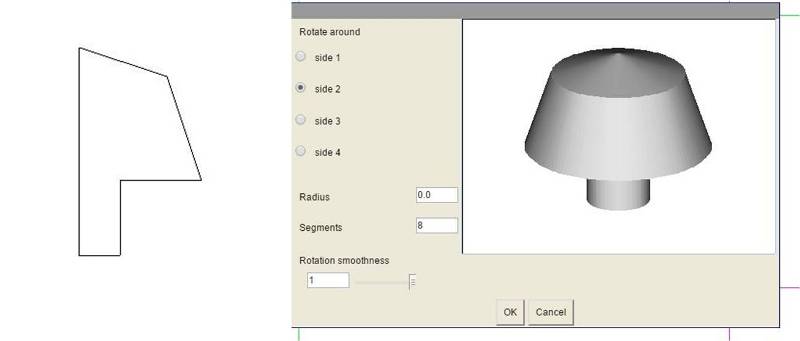
The following dialog window is displayed:
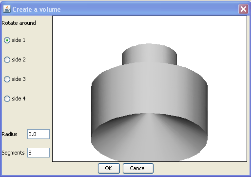
The "Radius" field allows specifying the distance from the axis of rotation when the initial curve is rotated. Default radius is 0, that is to say that we turn at the nearest point in the middle. If you increase the radius, more the hole in the center of the result will be large.
The "Segments" field determines the accuracy of the result. If this field is for example set to the value 3, the result will have a triangular shape rather than circular.
The default value of 8 is a good value for most of the typical use cases.
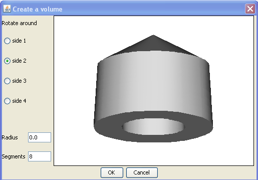
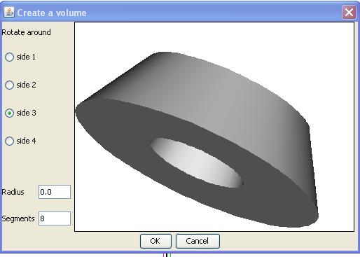
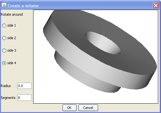
"Turn around the side 1, 2, 3, or 4" to determine the direction in which the initial curve is turned. You have to try different values in way selecting the one that gives the desired result. The figure below shows the results for the different options.
|
|
|
|
|
|
A smoothness parameter for rotation has been added to the tore tool.
By
default, when you draw a curve like for example the one below, and
then click on the tore tool
![]()
you get by default a revolution solid with the external surface defined by the selected curve. The default value is corresponding to the more current usage.
However, it is possible modifying 2 parameters, "Segments" and "Rotation smoothness".
The pictures below are showing an example of the obtained result when you change these parameters.

Create a hull form curves 
This tool allows you to create a hull fromcurves.
It can create any shape.
The curves must all be of the same type, ie all open or all closed.
The curves must all have the same number of points.
Take for example the following curves freehand, viewed from the front and right. They are all 6 points.

We
select the 4 curves and we click on the
![]() tool. The following dialog appears:
tool. The following dialog appears:
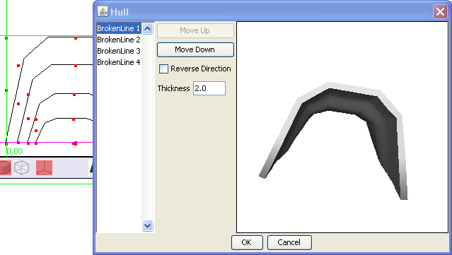
You can see on the left of the dialog window the list of the curves involved in the hull creation, in the order where they will be used to be linked. You can modify the order of the curves by clicking on the “Move up” and “Move down” buttons.
If you move, for example, the curve 4 to put it in first position, it changes the result as follows:
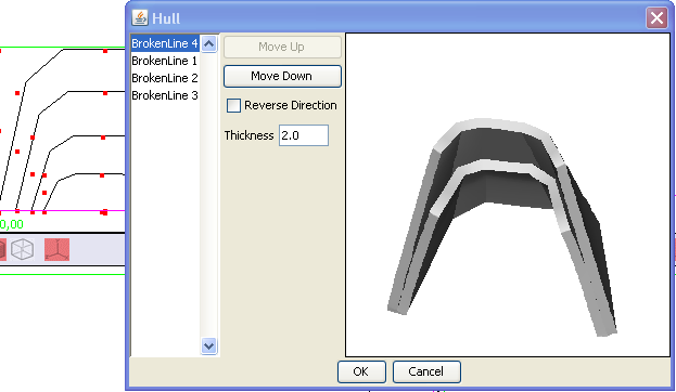
The coat goes from 4 to 1, and then to 2 and 3.
Reverse direction
This check box acts at selected curve level by crossing the lines created from the curves.
If, for example, you reverse the direction for curves 3 and 4 you get:

The last parameter is the thickness. It allows you to set the thickness of the hull.
Please note that the hull is thickened outwards. The size of the curves must be determined so that by adding the thickness of the hull you get the desired final dimensions for your object.
Milling with a solid transformed to a tool 
This feature allows you to achieve a removal of material having the shape you want, by using any solid tranformed to a tool.
You first create a solid with the shape, in negative, of the material to be removed.
You
then select this solid and transform it in a tool by clicling on the
button
![]() at
the bottom of the vertical toolbar. The solid becomes red to indicate
that it's now a tool. You can transform it again in a normal solid
by selecting it and clicking the same button.
at
the bottom of the vertical toolbar. The solid becomes red to indicate
that it's now a tool. You can transform it again in a normal solid
by selecting it and clicking the same button.
You
then position the tool in the solid you want to hollow out, and you
realize milling by clicking the button
![]() on
the vertical toolbar.
on
the vertical toolbar.
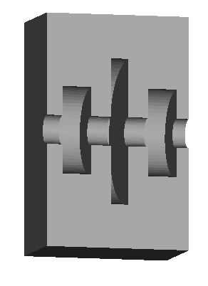
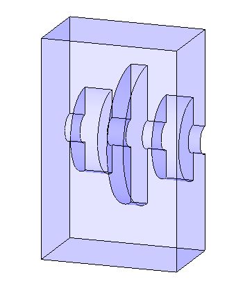
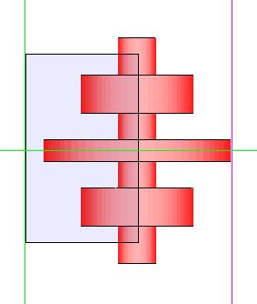
Suppose you want to achieve the part view below in shaded and transparent mode:
|
|
|
|
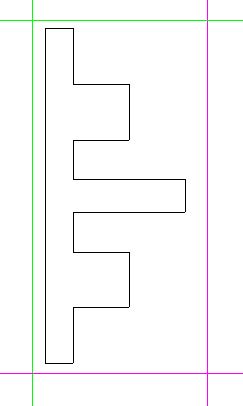
You
should first make a solid by creating a torus from a closed curve. We
draw point by point the below curve with
![]() and
then editing it point by point with
and
then editing it point by point with
![]() "Edit
object" in way to obtain a curve having the right shape and
dimensions.
"Edit
object" in way to obtain a curve having the right shape and
dimensions.
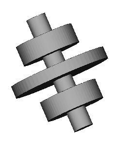
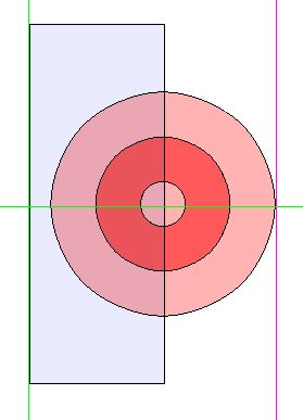
We
then make the solid that will be the negative of the material to
remove (
![]() tool).
tool).
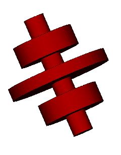
We
get the below solid that we will then transform in a tool (red color)
with the button
![]()
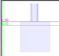
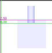
Then,
we make the cube/parallelepiped we want to mill (![]() )
and place the tool on the cube. Front and top view below:
)
and place the tool on the cube. Front and top view below:
When
the tool is correctly positioned, we click on button
![]() .
We get::
.
We get::
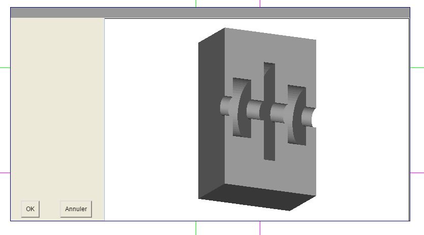
If the result is what we want, we can click on OK
We can then delete the tool or move it and we will see that we get the expected solid.
Guiding curve
Guiding curve 
This
tool is used to draw a freehand guiding curve for the « Thickening
along a guiding curve » tool
![]() .
.
The guiding curves are open curves.
A double click on the icon allows choosing the form of the curve: Angled, Interpolating or Approximating
If you foresee editing the curve before use, most typical case, then you should choose « Angled » which is the default value.
Transform a solid to a tool 
Allows the transformation of any solid in a tool allowing to mill another solid.
See: “Milling with a solid transformed to a tool”
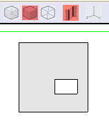
View
We
have seen in the "Vertical toolbar" that when you open the
drawing tool, it has four default views and that the "Select
View Layout" tool
![]() allows displaying one large view, 4 small views or 3 small views and
1 large view.
allows displaying one large view, 4 small views or 3 small views and
1 large view.
|
|
|
|
|
|

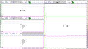
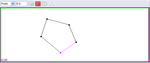
Each view, whatever the number, has the following layout
There is over each view a toolbar that allows you to perform actions in the context of this view.
In the view itself we have rules, two vertical and two horizontal, which will be used to position objects or tracing draws for cutting or drilling.
Toolbar
![]()
|
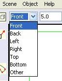
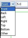
View position
To the left of the bar, a drop-down list allows choosing which side we see the object to this view "Other"
is displayed when the position is not determined. This is the case
when the view is rotated around the object with the tool
|
|
Zoom
Next
is the zoom on the object
![]() .
It should be set to the value allowing most comfortable view to
perform a given action.
.
It should be set to the value allowing most comfortable view to
perform a given action.
Rendering choice
A
group of 3 icons :
![]() allows selecting the object rendering.
allows selecting the object rendering.
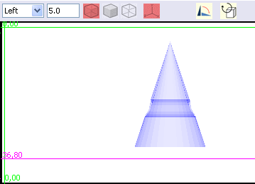
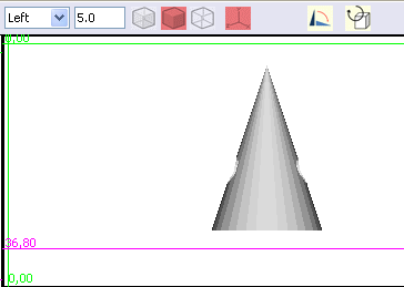
![]() Transparent mode
Transparent mode
|
|
This mode is useful for proper understanding of the cavities created inside the object. |
![]() Shaded mode
Shaded mode
|
|
This mode allows you to see the object in a form closer to reality. |
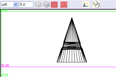
![]() Wireframe mode
Wireframe mode
|
|
This mode displays the "frame" of the object. Comparable to a tent frame. |
Outline
the objects edges
![]()
For the shade and transparent mode, set outlines on the edges of the solids.
|
|
|
|
Outline desactivated |
Outline activated |

Axis
display
![]()
Allows you to display or to remove in the view the axis indicating the directions of the width, height and depth.
Rotation
tools
![]()
Both tools allow for rotating (turning around an axis) the selected object(s) depending on the direction of the view in which it is applied.
With these two tools, you rotate the object as if watching it you were turning it by hand, without front or back movement. The axis of rotation is perpendicular to the view.
90°
rotation![]()
Each
click with the mouse on the icon
![]() turns the selected object(s) by 90° on the right (clockwise).
turns the selected object(s) by 90° on the right (clockwise).
Free
rotation
![]()
When
you click on the icon
![]() the herunder dialog window is opened
the herunder dialog window is opened
|
|
|
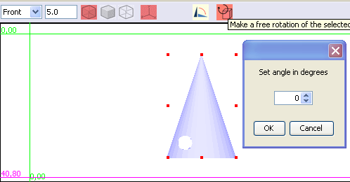
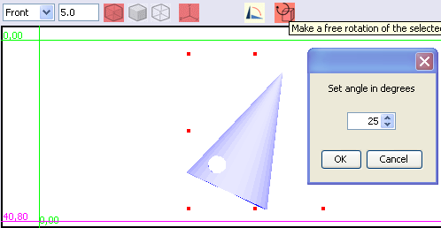
As you change the angle, the object rotates into view
Using rules
It is important to know how using the rules in order to make accurate measurements of objects or of the points where you want to saw or drill an object.
There are four rules for each view, two vertical and two horizontal. After loading of the window, the rules are arranged on the sides of the frame.
The operation of vertical and horizontal rules is the same.
There is a green rule, on the left at startup, and a magenta rule, on the right. Each rule has a number associated to it. The number associated with the green rule is always equal to 0. Green rule is still considered the origin.
The number associated with the magenta rule specifies the distance between green and magenta rule in millimeters with 0.05 millimeter accuracy.
To move a rule, you must click left on it and dragging. When you right-click a rule, it turns red.
Moving the mouse is used to position the rule approximately. It can be difficult to directly adjust the desired position with the mouse.
To enter a given position, you must double-click the rule, and the following dialog window is displayed:
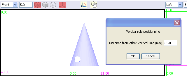
You must enter in this window the exact distance from the other rule you want to set.
This action can be performed on the green and magenta rules. It is always the rule that was double-clicked that moves. The new distance is always indicated by the number linked to magenta rule.
The distance entered in the positioning window still leaves the rule on the same side (left or right) compared to the other rule. If you want to position the rule on the other side, it is necessary to first move the rule with the mouse near the final position.
Curve editor window
This window appears when a curve is selected and that you select “Object/Edit Object” in the menu.
It allows editing a curve, i.e. changing the shape of a curve before using it.
The curves can be curves that you want to turn into solid, tracing curves or guiding curves.
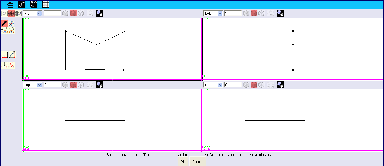
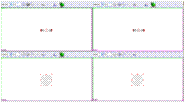
The Curve Editor Window displays at startup 4 views. In general, only the view where you can see the shape of the curve ("front" in the example above) is actually used. Other views only serve to verify that the changes that are done keep the curve in a plane.
It is possible to edit the curve to transform it so that it is no longer flat, i.e. in a plane, but it is an advanced use of the software and the subsequent use of these non-planar curves, for example to create a solid is more difficult to master. This case is not discussed in our documentation.
The commands available in this window are:
The menu bar at the top left of the window,
A vertical toolbar that occupies the left of the window
A toolbar at the top of each view.
You will find later in this document:
The description of the menu bar (Chapter "Menu").
The description of the vertical toolbar (Chapter "Vertical toolbar").
The description of a picture with its toolbar (Chapter "View").
Menu
![]()
Edit
Undo : Undo the last action. Shortcut : Ctrl+Z
Redo : Redo the last undo action. Shortcut : Ctrl+Y
Smoothing method
Allow selection of one of the 3 possible options for the curve smoothing method.
None: The curve cannot be smoothed. It is build with straight line segments.
Interpolating: the smoothing rounds the segment, letting them going through the points that are defining the curve. It is the recommended method if you want to smooth all or part of the curve.
Approximating: the smoothing rounds the segment by moving them away of the points defining the curve.
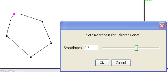
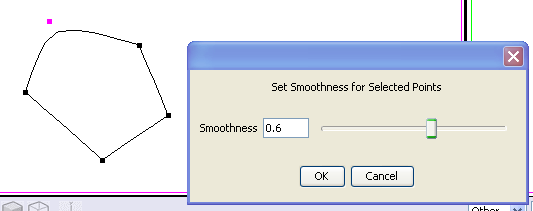
Set Smoothness
Displays a window allowing the smoothing of the curve for the selected points. You can either select some points or all the points of the curve.
Smoothing will be done according to the smoothing method described below, knowing that if no smoothing method is selected (“None” option), it will have no effect.
|
|
|
|
Smoothing for 1 point with “Interpolating” method. |
Smoothing for 1 point with “Approximating” method. |
Grids
Set a background grid for views. Shortcut: Ctrl + G
This command displays a dialog window allowing to define the grid characteristics.

Grid spacing: Spacing in millimeters between the lines displayed by the grid.
SnapTo Subdivisions: Indicates the number of subdivisions between grid lines. These subdivisions are not visible and are only used if " Snap to grid " is activated. If this option is enabled, an object that you move or change the size you will automatically move these subdivisions. For example, if the grid spacing is 5 mm and you set 10 subdivisions, the object will move 0.5 mm in 0.5 mm.
Show grid: Displays the grid when selected.
Snap to grid: Allows objects to automatically position on a sub division of the grid.
Vertical toolbar
The tools in this bar are the ones you'll use most often to edit a curve.
Here we are trying to describe the better we can the operation of these tools, but the best to master these tools, once the principle is understood, is to test it by yourself. You will find that by trying these tools that they are actually quite simple to use.
This bar contains four groups of tools that are described below from top to bottom.
Selecting the views layout
![]()
When you open the drawing tool, it has by default 4 views. This group allows you to display 1 large view, 4 small views or 3 small views and 1 large view.
|
|
|
|
|
|


One large view allows you to work with greater comfort on the details of the object.
With the display of four views, you can see the object simultaneously from multiple angles and to better understand the actions performed.
Display 3 + 1 is intermediate.
With practice, you will naturally select the layout that you feel most comfortable for the action you are performing.
Actions on the curve
![]()
The
tool on the left
![]() is selected by default.(
is selected by default.(![]() ).
It allows selecting the elements of a curve (points or segments) in
the view and moving the rules.
).
It allows selecting the elements of a curve (points or segments) in
the view and moving the rules.
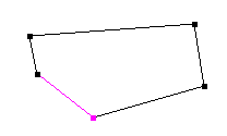
A selected element in the curve is recognizable by the fact that it is of red color:
|
|
For this curve, 1 point and 1 segment are selected. |
To select or deselect a segment, you left click on the segment. A left click on another segment deselects the previously selected segment.
To select a point you must left click on the point. To deselect, just click on another point or anywhere in the view, except for one segment.
To select multiple points:
Hold down the Shift key after selecting the first point
By left-clicking on a point of the view and dragging the mouse to include the points you want to be selected, if the topology of the curve enable it. Method to be used for selecting all points.
The
tool on the right
![]() allows a freehand move of the selected point(s).
allows a freehand move of the selected point(s).
It also allows you to select points or segments identically to the previous tool.
Actions on the view
![]()
The tool on the left is used to move horizontally and vertically the vision of the curve in the view. The curve doesn’t move. This can be compared to a camera that moves horizontally and vertically in front of the curve.
The tool on the right allows rotating the view around the curve. Again, the curve doesn’t not move. It can be useful if you decide taking the plunge and draw non planar curves.
Editing points

These are the four main tools that will allow you to draw a precise curve, by defining the length of the segments, the angle between two segments and adding or removing points in way do draw precisely the curve you want to get.
Segment
length:
![]()
You must select the segment and the extremity of the segment you want to move, and then click on this tool. A dialog window is displayed:
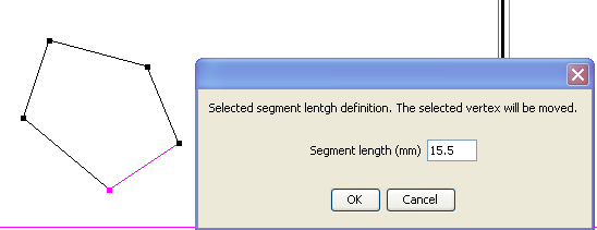
You will note the move of the selected point when you modify the length of the segment.
The icon is mnemonic. It shows that the selected point (red) is moving.
Angle
between 2 segments:
![]()
You must select a segment and the extremity of the segment around which the segment will rotate, and then click on this tool. A dialog window is displayed:
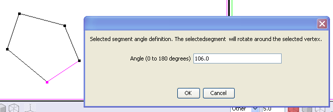
You will note the rotation of the segment around the selected extremity when you modify the angle.
The icon is mnemonic. It shows that the selected segment(red) turn around the selected point.
Adding
points
![]()
This tool adds a point between 2 contiguous selected points. It is possible selecting several pairs of contiguous points.
As seen previously, the selection of the first point is done by left click with the mouse and the following points by maintaining the Shift key + left click, or by dragging with the mouse.
Delete
points :
![]()
Delete all the selected points.
View
We
have seen in the "Vertical toolbar" that when you open the
drawing tool, it has four default views and that the "Select
View Layout" tool
![]() allows displaying one large view, 4 small views or 3 small views and
1 large view.
allows displaying one large view, 4 small views or 3 small views and
1 large view.
|
|
|
|
|
|


Each view, whatever the number, has the following layout
There is over each view a toolbar that allows you to perform actions in the context of this view.
In the view itself we have rules, two vertical and two horizontal, which will be used to position the points of the curve.
Toolbar
![]()
|
View position
To the left of the bar, a drop-down list allows choosing which side we see the object to this view "Other"
is displayed when the position is not determined. This is the case
when the view is rotated around the object with the tool
|
|
Zoom
Next
is the zoom on the object
![]() .
It should be set to the value allowing most comfortable view to
perform a given action.
.
It should be set to the value allowing most comfortable view to
perform a given action.
Rendering choice
A
group of 3 icons :
![]() allows selecting the object rendering of the scene when the
“view/show/Full scene” option of the menu is selected.
allows selecting the object rendering of the scene when the
“view/show/Full scene” option of the menu is selected.
![]() Transparent mode
Transparent mode
![]() Shaded mode
Shaded mode
![]() Wireframe mode.
Wireframe mode.
The selected rendering doesn’t impact the edited curve.
Axis
display
![]()
Allows you to display or to remove in the view the axis indicating the directions of the width, height and depth.
It is important to know how using the rules in order to make accurate measurements of objects or of the points where you want to saw or drill an object.
There are four rules for each view, two vertical and two horizontal. After loading of the window, the rules are arranged on the sides of the frame.
The operation of vertical and horizontal rules is the same.
There is a green rule, on the left at startup, and a magenta rule, on the right. Each rule has a number associated to it. The number associated with the green rule is always equal to 0. Green rule is still considered the origin.
The number associated with the magenta rule specifies the distance between green and magenta rule in millimeters with 0.05 millimeter accuracy.
To move a rule, you must click left on it and dragging. When you right-click a rule, it turns red.
Moving the mouse is used to position the rule approximately. It can be difficult to directly adjust the desired position with the mouse.
To enter a given position, you must double-click the rule, and the following dialog window is displayed:

You must enter in this window the exact distance from the other rule you want to set.
This action can be performed on the green and magenta rules. It is always the rule that was double-clicked that moves. The new distance is always indicated by the number linked to magenta rule.
The distance entered in the positioning window still leaves the rule on the same side (left or right) compared to the other rule. If you want to position the rule on the other side, it is necessary to first move the rule with the mouse near the final position.